Posted: 7/20/2020
Proposed here are systems comprising both direct and indirect means of converting solar energy to desalinate water. Both means comprise thermal transfers. These systems comprise solar PV panels to provide indirect solar thermal heat by powering a heat pump, and direct solar thermal heat by using the absorbed heat, that is normally wasted in PV panels, to drive an evaporation and condensation cycle. Further, the latent heat of condensation is used in the process by the heat pump to move this heat energy to drive the evaporation stage. In the ideal case, energy is not wasted, which yields high efficiency. These systems can be more efficient that direct solar thermal, and more flexible, as described below.
Currently, PV panels are about 20% efficient. If a heat pump operates between two thermal reservoirs with a small thermal temperature difference, it can operate at a relatively high coefficient of performance (COP). A COP of 4 is achievable for this low temperature difference, or even higher. At a COP of 4, a heat pump is equivalent to a solar thermal collector that is 80% efficient, which is very good. However, the heat absorbed by a solar PV panel can also be harvested, which means that a PV panel and heat pump combination can do better than a pure solar thermal collector, when this absorbed heat is used. Also, PV panels are getting more efficient. As of this writing, it looks like tandem silicon perovskite PV panels will jump to the 25% range, which means an even larger thermal advantage for PV over thermal-only collectors. Multijunction cells in the future may provide even higher efficiencies. The point here is that PV driving a heat pump now, or in the near future, can outperform pure thermal processes. Along with a performance advantage, a heat pump-based method can be run with other forms of electricity, when the sun in not shinning - adding flexibility.
The described systems also use a partial vacuum to reduce the pressure of the saltwater to lower the phase change temperature, which is the temperature of the evaporation and condensation cycle. This lower phase change temperature enables an equilibrium of heat transfer in the ratio of incoming radiant energy gain to the heat lost from the exiting fresh water, and conductive loss and radiant emittance. This temperature is also conducive to running a heat pump with a high COP.
This first described system directly uses water as the phase change material driving a heat pump cycle. Following below is another version of the same concept that uses a more conventional heat pump, as well as other means of transferring heat.
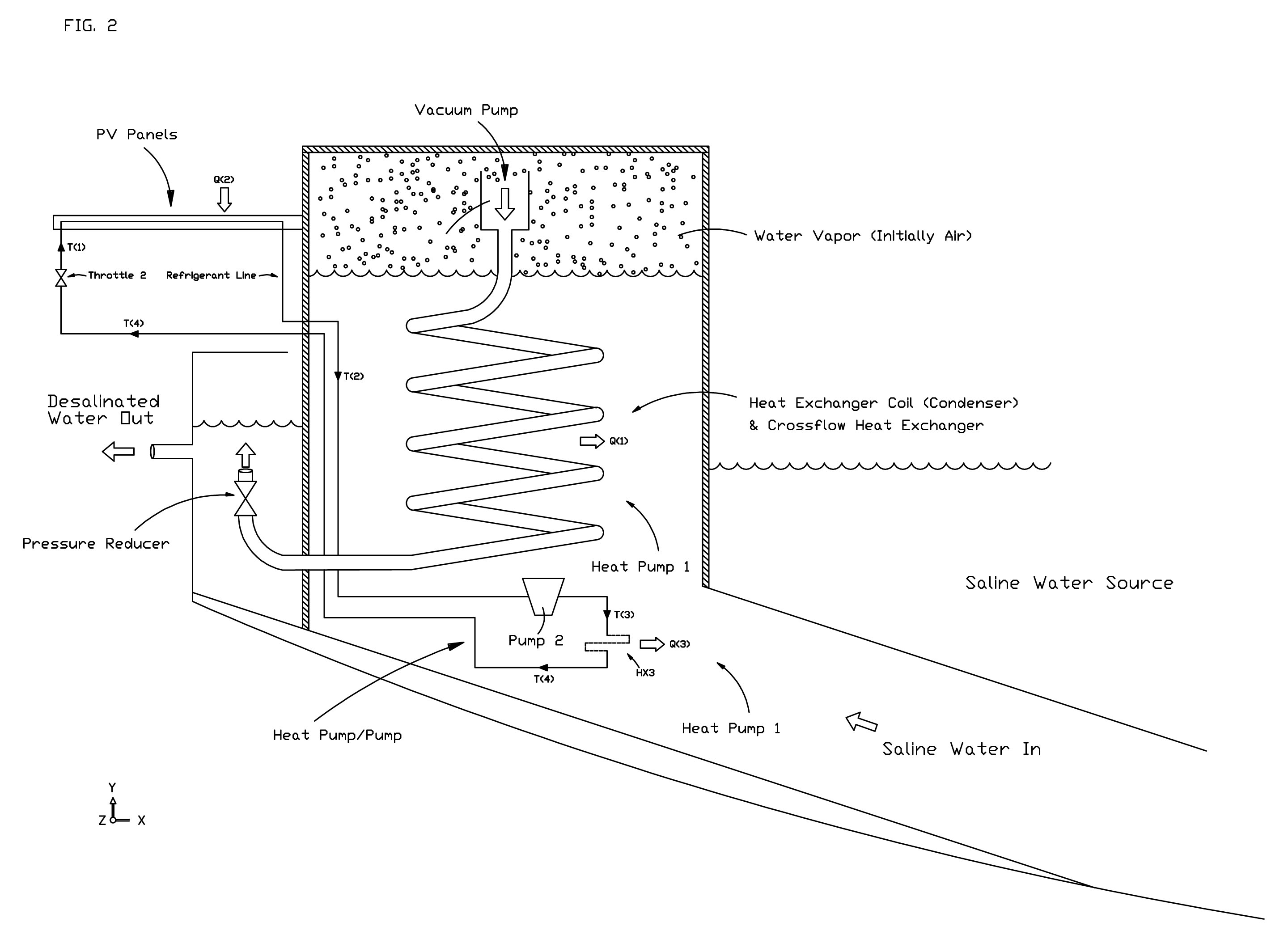
Initially, the vacuum pump pumps air out of the main chamber lifting up the saline water source (usually seawater). A partial vacuum is created lowering the phase change temperature and the space at the top is filled with water vapor. The water vapor is then pumped into and through a heat exchanger coil, which is a condenser, toward a throttle, or other pressure reducer. Pressure builds up and the water vapor condenses. During condensation, heat is released and the coils move heat back into the saline side.
The temperature of the sources need not be at a high differential, and the COP can be commensurately high. A COP of 4 or higher is achievable. At this rate, the source of electricity to drive the heat pump would only need a quarter or less of the energy needed to evaporate the water.
The source of electricity in this embodiment is one or more PV panels. The panels provide electricity, but they also are a source of heat energy.
In this concept, and also in the concept below, heat energy is moved into input saline water source by circulating a fluid. In FIG. 2 this is depicted as a heat pump, but it may not comprises a phase change, and the fluid is not limited to a refrigerant. Since the heat source may be warmer than where the heat is moved to, a heat pump is not required, but may be useful.
Both the heat from the PV panel, and the electricity from the PV panel that is turned into heat help bring the system up to working temperature, and provide heat for the evaporation phase. Gravity and the resultant heat gradient move the heat to the top in this design, where the heat is used for evaporation.
This first concept is simpler than the one that follows. It directly uses the water vapor as the refrigerant.
Second Desalination Device: Posted: 7/19/2020
This second device described uses multiple processes. In the design, one or more heat pumps move heat from the desalinated water to the saline water. The heat energy goes into the water vapor that vaporizes due to this input of heat. The vapor will condense due to one or more processes on the desalinated water side. One method is through conduction through the top cover, as happens in a conventional solar still, although, this is optional. The second is through condensation at the surface of the desalinated water that is cooled by the heat pump. (A conductive path may also be provided that increases the surface area for condensation.) The heat absorbed in evaporation is then transferred into the desalinated water, which is then moved back to the evaporative saltwater side from the latent heat of condensation by the heat pump. One heat pump drives both the evaporation and condensation processes.
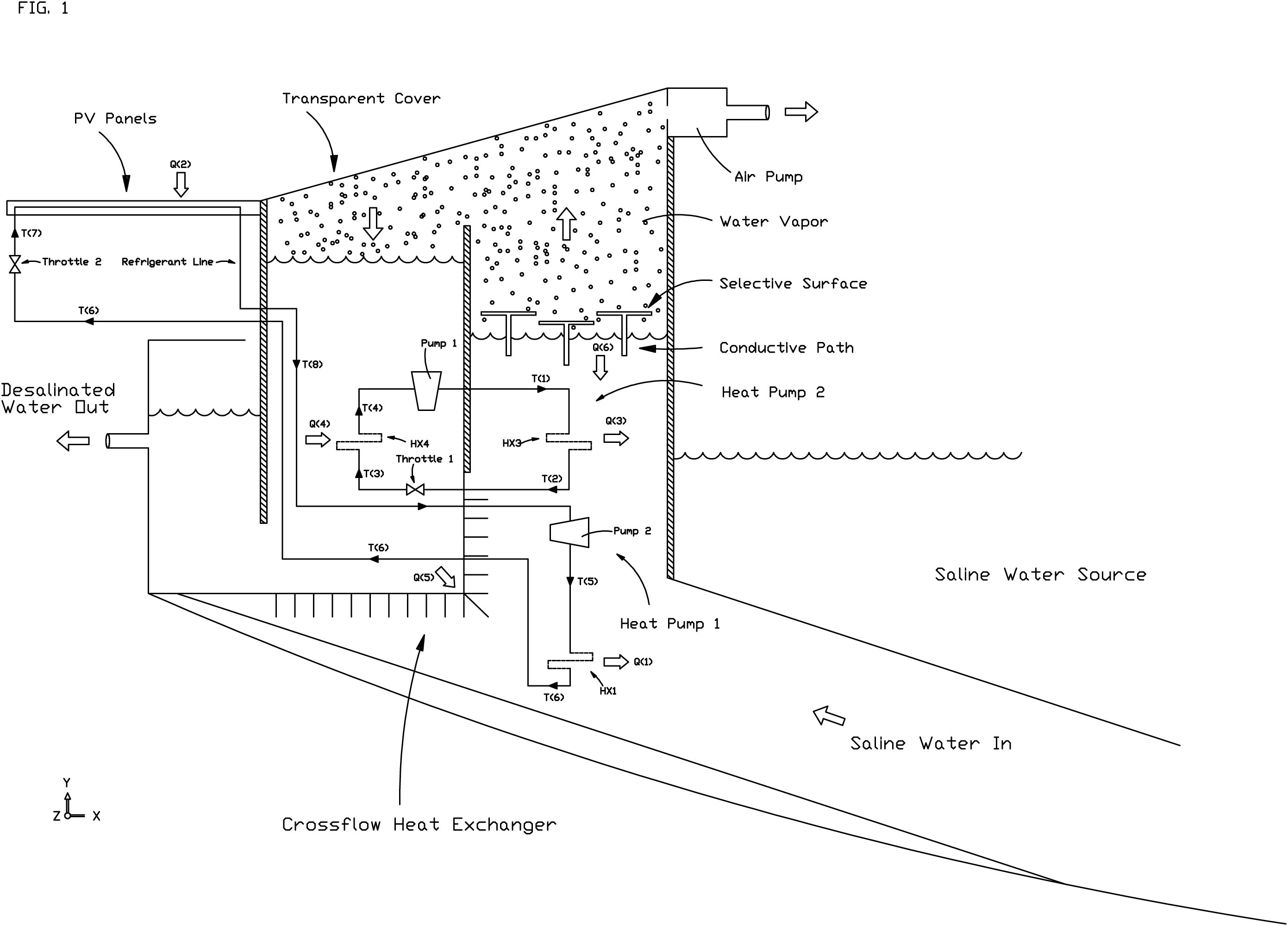
FIG. 1 illustrates the concept. The Air Pump in the upper right initializes the system by drawing saline water in from its source, and desalinated water in from an initial supply. Once initialized, the air pump only needs to maintain the partial vacuum it created. This would come from gases that manage to diffuse through the input and output water supplies, and should not be substantial. The partial vacuum has multiple purposes in this design. One purpose is to lower the temperature of the phase change and evaporation condensation cycle, as previously stated.
Once the partial vacuum is created, it will draw up two columns of water, with the input being the saline water, and the output being the desalinated water. The water in the two columns are exposed to heat exchangers which exchange heat from the PV panels and from the desalinated water to the saline water. FIG 1. Illustrates four sources of heat exchange to the saline water. All are not required, but they are all useful. Due to gravity, heat will rise in the columns. This is another purpose of the partial vacuum, as it keeps the heat energy rising, and at the surface. This also limits heat diffusing out of the system through the input and output water, reducing loss. In this figure, there are two common coils that transfer heat to the incoming saline water, and two sources that conduct heat in without a heat transfer fluid. Heat transferred at Q(5) is shown as common conductive fins. But this can be any common heat exchanger means. This comprises a common and known method of crossflow heat exchange to move heat from the output water to the input water. Heat exchange in any crossflow heat exchanger is not complete. As such, it might be beneficial to have another heat pump transfer heat out of the output water to the input water after the output water has exited the crossflow heat exchanger. This is not shown, as this proposal is currently at the concept stage.
Heat exchanger HX1 at Q(1) transfers heat input at Q(2), which is the evaporator in the PV panel. The PV panel not only transfers heat to the input water, but the temperature of the input water cools the PV panel keeping the PV efficiency high.
Heat exchanger HX3 at Q(3), which is a condenser, transfers heat Q(4) input at HX4, which is the evaporator in the output desalinated water. This heat exchanger HX4 should be up high at the top of the desalinated water. It is only shown lower to keep the drawing simple. Similarly, heat input at Q(2) from the PV panels is transferred to the saline water at Q(1). In this figure, the PV panels provide the electricity for both heat pumps (1 and 2). Although, supplemental forms of electricity may be used. Provided a transparent top cover is used, selective surfaces may absorb the incoming solar radiation and directly convert the radiation to thermal heat and conduct to the incoming saline water via some conductive path. In this case, both PV direct and indirect heating, and direct solar thermal heating are used concurrently and in combination. (It is also possible to use a selective surface that cools, as these are now available, on the condensing side.) However, the top cover being transparent is optional, and if omitted, then there is no need for selective surfaces. See notes below.
Regarding costs, if $0.10/KWh is assumed as the cost for commercial PV, and a heat pump COP of 4 is assumed (which is reasonably for a low source temperature differential), and the energy for evaporation is 0.000628 KW-h/g, then the cost comes out to: $0.059 per gallon This, of course, is the operating cost based only on accepted costs of PV generated electricity. However, it should be noted, that there is not much to wear out. There are no membranes to maintain. A water desalination plant could be constructed that could work for decades into the future. Further, the PV panels could be replaced with higher efficiency models in the future, lowering costs.
Notes:
The drawing shows a flat glass top. Obviously, this would crack under the pressure difference in this design. The glass can be arched, which solves this problem. It isn’t shown in the drawing just to keep the idea easily understandable.
Also, the glass top can be replaced with insulation, or a double cover. The design depicted has radiant solar gain through the glass top, but it also has conductive and convective loss that helps condense the water. Full modeling has not been done, and it is unknown at this time what is most beneficial. Regarding the vacuum pump. It is needed to bring the system to its initial state. After that, it is just needed to maintain the partial vacuum, which can probably be done at night when there is low water vapor. Maintaining the low pressure comprises removing gasses that can diffuse through the water, which is a small amount. As such, it shouldn’t require much operating power. But this is an unknown at this time. Regarding PV panels, due to the partial vacuum of the system, the operating temperature does not need to be particularly high for the water to phase change. Thus, PV panels could be inside the device. Also, using PV panels to provide electricity means that other forms of electricity can be substituted at times of low solar radiation. This give the system flexibility.
Regarding the two depicted heat pumps, the function of the two heat pumps can be combined into one, with one refrigerant line connecting. It might also be possible to eliminate pump 2 and/or throttle 2. The reason for the extra steps is that there are multiple heat transfers and exchanges that can be utilized. It also might be more beneficial to change the order, also in regards to height, of the heat exchangers in the incoming water. Also, another heat pump can be added after the crossflow heat exchanger. An advantage of the design is that in a column of water, heat will rise. Water, in particular, has a strong gradient. Heat transferred into the salient water side from the one or more heat pumps will rise to the top due to gravity.
Also, I have left out any filtering of the desalinated water, as this would be the same as other designs. Regarding the brine that is generated, this design uses height to maintain the partial vacuum. This height provides gravity as a force that helps diffuse the salt and other minerals of the saline water downward and back out, while water diffuses upward, as water is lighter. Whether or not saline input water needs to be pumped through the input flow, or by how much is not known at this time, as this is just in the concept stage.
Regarding heating the saline input water, heat from other sources can be used to at least partially bring the saline water up to the phase change temperature. A source of heat, such as from an industrial process, can be used at night, when solar heating is not available. Further, solar energy, or any other source of renewable power can be stored and then used at night to drive the process. Other sources of electricity can also be used, such as excess power generated at night. An advantage to this system is the flexibility of power and heat sources that can be used.
Water Height:
Most of the solar thermal solutions for desalinating water generate water at the same height as the incoming seawater, or the height it has been pumped to. This is generally undesirable. In an advantage, the height of the fresh water in the present design can be above the height of the incoming saline water. The figure shown only shows a small height difference, but it can be greater providing the output water with pressure to move it to where it needs to go. Full systems should be evaluated, and not just a desalination process in isolation. In this regard, the advantage of height this method could provide should be taken into account. (Note: Due to the weight of saline water being greater per volume, the difference in height on the incoming side will be slightly smaller than the height difference of the fresh water side. But it is a small difference.)
Provided desalinated water needs to be produced at a significant height, I propose the following process: Solar Desalination using humidity condensation: (Posted 6/16/2020)
Desalination is generally done for us. Salt water sources are almost always large, and the Sun extracts pure water from salt water and deposits it in the atmosphere as humidity. All that is needed is to efficiently extract the water from the air.
To do this, I propose using a novel method that extracts water at night. This comprises using solar PV panels to drive a pump to store energy as compressed air, which in other applications is an inefficient method of storage. But in this application, the heat transfer that is usually wasted is put to good use. The compressed air is used to cool airflow though ducting in two ways, which I will explain shortly. The novel concept presented here is to move atmospheric air through ducting and a series of steps and processes that cool the air to get the water vapor in it to condense. The first process is simply to take advantage of the daily temperature cycle. In short, it is significantly cooler at night. This invention takes advantage of the fact that relative humidity rises at night, and the nighttime temperature is closer to the dew point - so it takes less energy to condense water from cooler night air.
The next step is to pass the air under the PV panels. PV panels are covered in glass, which just happens to have a high (and excellent for this application) emittance in the infrared range - higher or equal to 90%. Thus, PV panels can actually be used to cool the nighttime airflow.
The next step is to conduct heat from incoming air after it is cooled by the PV panels to the cool exit air.
The next step is that the airflow flows past the compressed air tanks, which should be finned. As the stored compressed air is expanded, it cools the airflow. Heat is transferred into the tank in the process, which improves the percentage of work energy that can be returned. This makes this process near-isothermal, which is efficient.
The work energy from the compressed air storage then drives a heat pump, which cools the airflow further. Also, it can drive a fan to move air through the ducting. How much goes to the fan, all depends on how much the air needs to be cooled to reach condensation. So, it depends on the atmospheric conditions. The last step is to conduct heat from incoming air after it is cooled by the PV panels to the cool exit air. This is the same step as above. One other aspect that can be used is to orient the process in the direction of prevailing winds.
There is not a lot of detail here, as this is just at the concept stage. But this design takes advantage of cool night time air, and the advantageous nature of heat pumps that move more heat energy than they consume. This method also uses the heat transfer in the storage step to advantage.
There is also the advantage to the method of extracting water from air that it can be done at a height. Height provides water pressure that would otherwise take more energy to gain. The energy use of the full system needs to be accounted for, and not just for the step of desalination. Provided extracting water from air is done at a height greater than is needed for the desired water pressure, energy can be extracted from this. So, if there is a convenient mountain, or even a tall building, this method yields a significant advantage. Another advantage is that condensing water from air that is up high contains less biological matter, such as viruses.
IP:
These designs, processes, and inventions are being publicly disclosed. IP is not being pursued. The purpose of this disclosure is to stimulate progress, as desalination will become very important with the changing climate.