Disclosed here is a combined heat pump (HP) and heat recovery ventilator (HRV) utilizing a novel air cycle. HRVs are heat recovery devices that recover some of the heat or cold lost from air that is transferred between the inside and outside of a building. Common practice is to install a common heat pump and an HRV. However, an HRV can be turned into a heat pump by replacing a fan with a compressor and expansion turbine to make a heat pump cycle using air instead of refrigerant.
It is important to note that this air cycle is NOT a reverse Brayton cycle. Reverse Brayton cycles can be looked up in engineering books, where one will find that they have poor efficiency. The air cycle used in the described HRV device has different heat transfer steps.
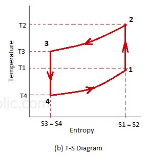
If one looks at the right side of a T-S diagram of a reverse Brayton air cycle, one will see that the compressor has to first raise the temperature across the temperature differential between the inside and outside heat sources (T1-T3). Then it needs to raise the temperature farther (T3-T2) to push heat across the heat exchanger.
By contrast, the compressor of the device described here only needs to raise the temperature and pressure by a smaller amount for the same amount of heat transferred. The reason for this is that an HRV comprises a heat exchanger where heat is transferred between incoming and outgoing air. This is generally done through a crossflow heat exchanger, but in this described device it will be done with a superior counterflow heat exchanger. The temperature differential across the heat transfer plate of a counterflow heat exchanger is much smaller than the temperature differential between inside and outside. Because of this, the compressor in this air cycle does not need to work as hard increasing pressure, and thus temperature, of the outgoing air to push heat across the heat transfer plate. The greater the inside to outside temperature differential, the greater advantage to this cycle over the reverse Brayton cycle shown in engineering books. I would give you a name for this cycle, but I can't find one. ("Temple" cycle?) Being a different cycle, one should not assume it has the poor efficiency of the other.
Another difference of this cycle is that it can be an open cycle. It is open to both the inside and outside, whereas a reverse Brayton cycle can be an open cycle, but only open to one heat source. This is different, which again makes it a different cycle.
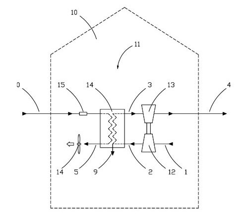
The drawing above shows an engineering schematic. Inside air 1 flows into a compressor 12. The compressor compresses air through one side of a counterflow heat exchanger 14. The air then flows trough a turbine 13 and exits outside 4. The turbine uncompresses the air and recovers some work energy. This is similar to a common air cycle heat pump, but yet also different. The compressed air heats up, and that heat is transferred though the counterflow heat exchanger to the incoming air. Fan 14 pulls the incoming air 0 through the heat exchanger. This side is the same as the incoming side of an HRV that uses a counterflow heat exchanger. In an HRV with a counterflow heat exchanger, the temperature differential (deltaT) across the heat exchanger plate is lower than the the deltaT of outside to inside air. Thus, the compressor does not have to raise the temperature as much as a common air cycle to push heat across the heat exchanger.
The diagram above shows the cycle being used to add heat in Winter. However, the cycle can also be used to cool. It also can be accomplished in several ways. The diagram depicts a compressor that raises the pressure of one side of the heat exchanger. However, the placement of the compressor and turbine can be reversed and one side of the heat exchanger can be cooled with lower pressure, which could be called a "pull" method, as opposed to the "push" method described above. Further. both sides of the heat exchanger could have pressure changing compressors and turbines.
RESULTS
I have modeled this cycle in Excel to determine COPs for different cycles and conditions. It is important to note that this device does two things. First, it recovers heat from the inside air exchanged with the outside air, and second it acts as a heat pump. It is also important to note that buildings require air exchange, often measured in air changes per hour (ACH). What I found is that this device compares well to an HRV and heat pump that is recovering heat from the air exchanged with the outside and transferring heat lost from the exchanged air. For the conditions of 295K inside temperature, 280K outside temperature, and a pressure ratio of 1.2, the combined HRV Heat Pump works at a COP of 4.2, whereas a conventional HRV and heat pump deliver a combined COP of 3.6 (for a heat pump with COP 3.5), or 4 (for a heat pump with COP of 4). Note: I used efficiencies of 85% for the compressor, turbine, and counterflow heat exchanger. These are at the high end of what is possible, as I am looking at what is possible with careful design.
Using the same values, except for lowering the outside temperature to 255K (0°F), the combined device gives a COP of 6.6. By comparison, a conventional HRV and heat pump combine for a COP of 2.4 (for heat pump COP of 1.5) and 3.1 (for heat pump COP of 2). In really cold weather, conventional heat pumps struggle. They have their outside coils freeze and usually require defrosting cycles that hurt efficiency. By contrast, this combined device does not have coils to freeze. It has a turbine that spends half its time exposed to slightly warmer temps than the colder air it pushes out, and it spins, so it can spin off condensation. The reason for the high COP of this combined device is that the HRV counterflow heat exchanger is doing the majority of the heat transfer, which does not happen in conventional heat pumps.
But that is the good news. The other side of the coin is to look at how the combined device works only as a heat pump. That is, if the proper amount of ACH/infiltration has been met, how does it perform as a heat pump while transferring more air with the outside. Here the results aren't as good. For an outside temperature of 280K, the COP is 2.1. It drops only to 1.8 at 255K though. From what I have seen, seasonal averages for heat pumps are only in the range of 2-2.5. This makes sense as the majority of the heating is required when the outside temperature is below average. Though it may be that this combined device could outperform a conventional heat pump when they have frosting problems.
So what I conclude is that a combined HRV Heat Pump deserves a more detailed look, especially for spaces that have a need for high air change ACH rates. But probably not for replacing an existing heat pumps.
Regarding cooling, as expected, the COPs are about one point lower. Using the same 295K inside temperature, a 310K outside temperature, and a pressure ratio of 1.2, I came up with a COP of 3.2 for the combined process, and only 1.3 when acting as AC alone when a space has no need for more forced air exchange. In modern homes, infiltration/ACH accounts for roughly a quarter of undesirable heat loss/gain. But it is more in a super insulated building. In the future, it is possible to create buildings with net positive envelopes. (See: Radiant Roof) It looks quite possible to equip such a building with only a combined HRV Heat Pump.
I am happy to share the excel file with anyone who would like to see it.
Will Temple ME (willtemple (at) flickkey.com)